Traffic light switching
The aim of this project is to simulate a traffic light and to switch it with a button.
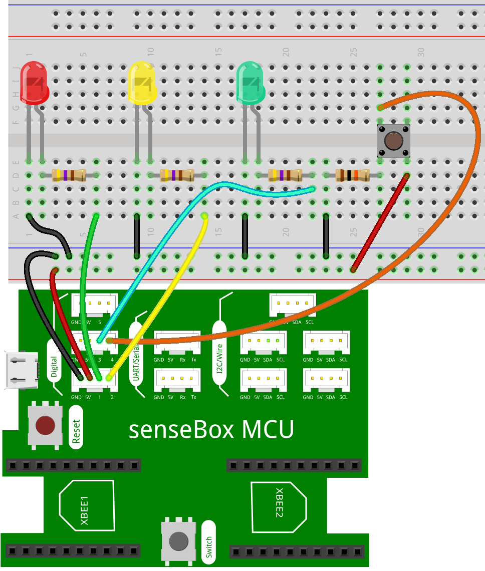
Assembly
To connect all components, you need two JST adapter cables. The first is connected to digital A (i.e. digital pins 1 and 2), the second to digital B (i.e. digital pins 3 and 4). The red and yellow LEDs are connected to the cable in Digital A, the green LED and the button are connected to the cable in Digital B.
Programming
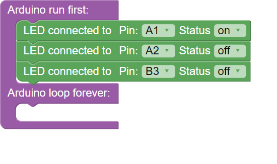
Step 1
In the setup() method, set the red LED to ON and the other two LEDs to OFF to initialise the programme.
Step 2:
Now write the loop() method. This is where your actual traffic light circuit is programmed.
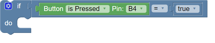
At the beginning of the loop() function, you are asked each time whether the button is pressed.
This query happens in a when-make-block, if it is true (the button is pressed), the program code is executed within the make-block.
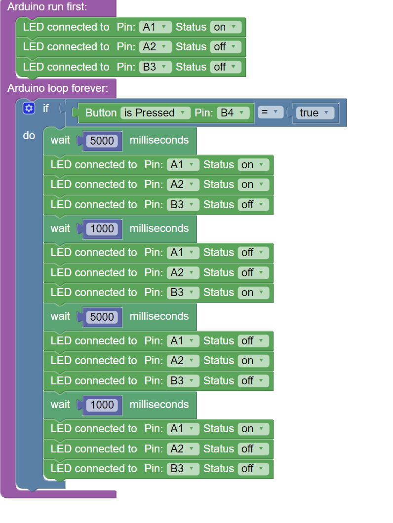
Step 3:
Here you start by waiting 5 seconds. Then switch on the red LED (already switched on) and the yellow LED, the green LED remains switched off.
Then wait for 1 second and switch on the green LED only, switching off the red and yellow LEDs.
After another 5 seconds, switch off the green LED and switch on the yellow LED. The red LED remains switched off.
Now wait another second and then switch on the red LED and switch off the other two.
You have reached the end of the if-condition. The programme now remains in the current state and does nothing until the button is pressed the next time.
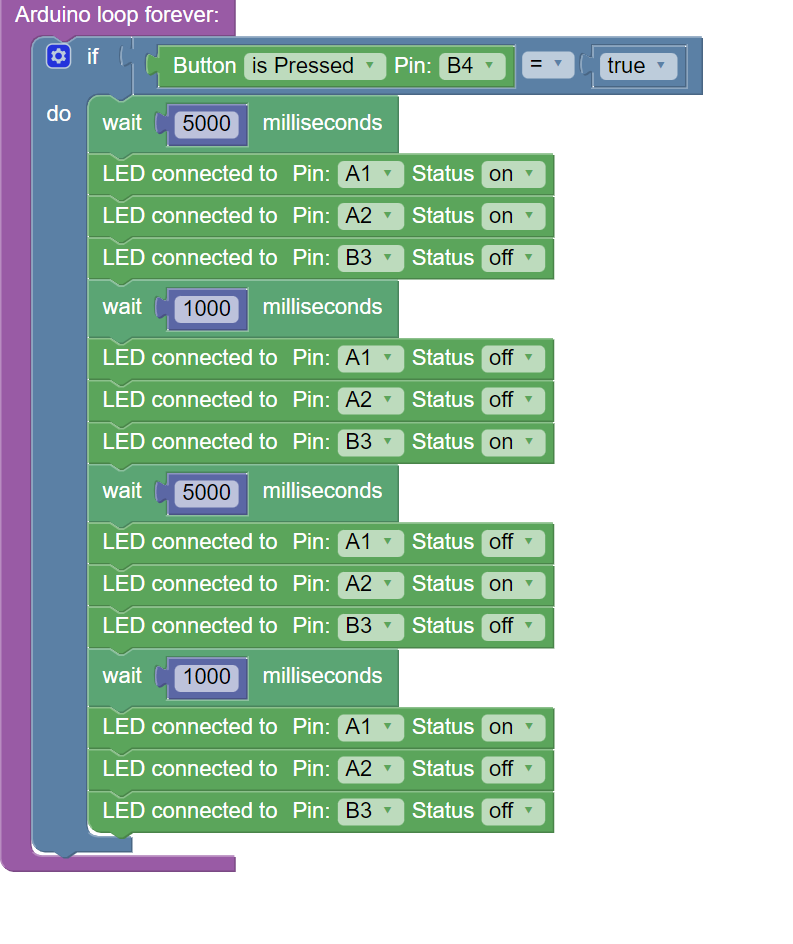
Entire code
Here you will find the entire code again as a coherent block.